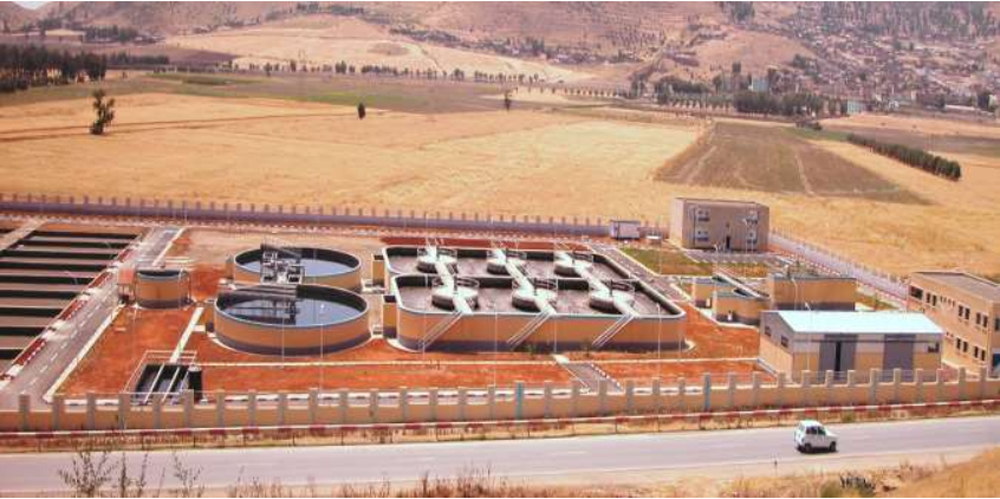
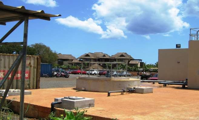
PLANT

750 m3/h Sugar Canes Grinding Company For Sugar Industries In PAKISTAN:
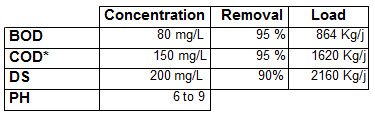
* We can guarante this value only if the COD is removable by a biologic action.
We guarantee these results thanks to our process, insofar as:
- The basic data indicated in our calculation note are respected
- The station is used under normal conditions
- Minimal maintenance is assured.
This project sets out our proposed wastewater treatment for a domestic wastewater treatment plant.
The treatment process is presented as follows:
- 1 water lifting station with three submersibles pumps is existing
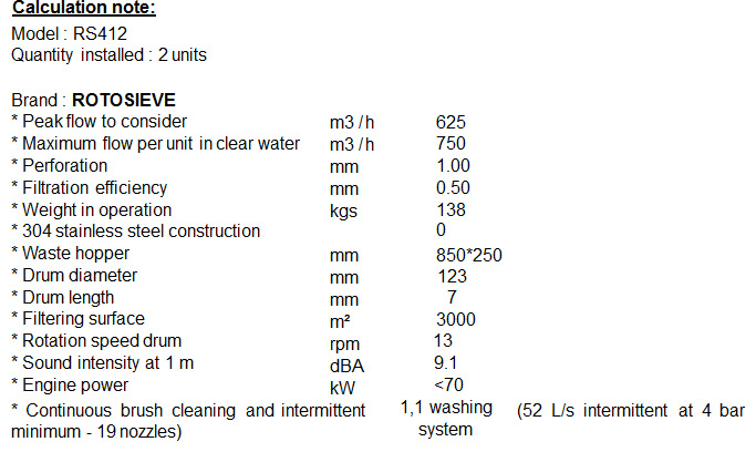
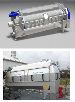
- 2 rotatives screeners
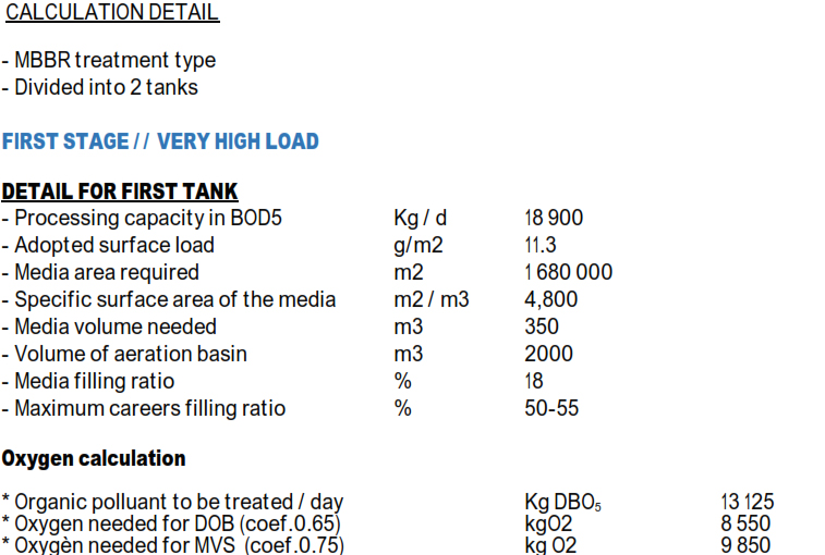
- 2 aeration tanks in MBBR mode serial MBBR PROCESS
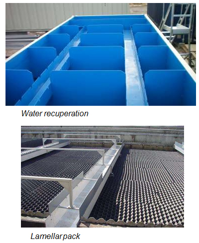
- 5 lamellar decanters in containers
- 1 sludge pumping station
- 1 Ultrasonic flowmeter and venturi channel [optional]
- 1 Sampler [optionnal]
- 1 sludge storage tank
- 1 Screw press for sludge dewatering [optional]
- 1 polymer preparation and dosing system
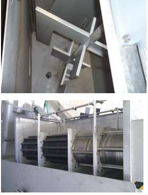
Wastewater is admitted inside a perforated drum equipped with a waste conveying screw. Mesh perforation: 1.00 mm which ensures a fine filtration at 500 microns with a risk of clogging very low.
This fine physical separation will make it possible to recover 90% of the macro-molecules of size highter than 500 µm. These will be drained into the drum before being compacted in the compactor.
2 screeners is the most safe solution. But if you need reduce price, only one model upper sized could reach the filtration goal.
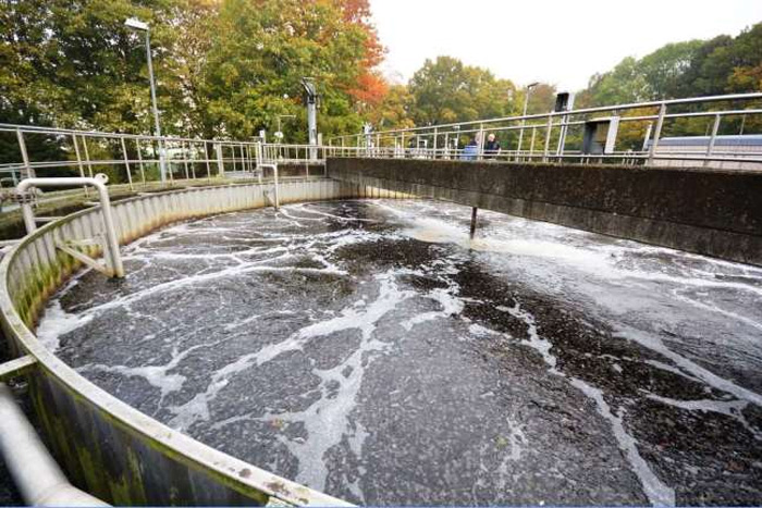
The treatment plant presented in the following memorandum operates according to the principle of prolonged aeration.
Given the need to provide for the use of the minimum space possible, we have planned the implementation of the process in reinforced concrete ponds, to be built on site, according to the plans of forms that we will provide.
In order to reduce the volumes, we used for the aeration part, mobile immersed supports to fix the bacteria and for clarification part, two lamellar decanters.
This principle is implemented as follows, for each line of treatment:
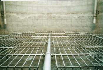
The wastewater is introduced into an aeration tank, in which the bacterial floc is maintained. A set of air diffusers ensures the efficient mixing of the entire liquid mass, as well as the transfer of oxygen from the air, by injection atthe bottom of the tank.
This double action of the air diffusers allows the biological treatment of the water and the mixing of the entire volume.
The effluent is introduced into a reinforced concrete basin having the shapes indicated on our plan. It is important to note that the area occupied by these basins is inversely proportional to their height. Depending on the means of the company chosen to build these basins, it will be possible to reduce the space occupied by the station.
In this volume is a quantity of small plastic supports, intended to receive the aerobic bacteria which will ensure the aerobic treatment process, according to the following principle:
It's a biological treatment on " in-water " fixed culture and moving with evacuation of biomass over water. The fixed biomass developed on the lining is brought into contact with the substrate and with the blown air. The latter ensures the transfer of oxygen, the agitation of the packing and the liquid phase as well as the regeneration of the bio-film by detachment of the biomass. To separate the purified water from the sludge formed, the effluent will then pass into two lamellar decanters.
Sludges will go gravitary to the lamellar settlement system. After sedimentation, sludges will do to the sludge storage And clarified water to the outlet.
After pretreatment, the effluents are admitted into an "aeration tank" where sewage and sludge will be treated simultaneously.
The air blown by diffusers in the lower part of the basin creates a rising current in the liquid mass and a sweeping over the entire bottom of the structure thus reducing all the submersible media in the vicinity of the diffusers.
The fine bubbles during their rise allow the transfer of oxygen to the liquor.
Accumulation of excess sludge inevitably occurs, they will be extracted periodically after the liquor has passed through the lamellar decanters.
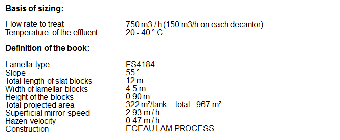
Biological packings consist of a series of small plastic modules.
This support intended to be immersed in the containers has a very large area developed for the colonization of bacteria with a high void percentage to avoid clogging.
When the bio-film deposited on the supports reaches a certain thickness, it falls off in pieces under the effect of the gases formed in the zone of contact with the support and the turbulence created by the air bubbles.
This is the process of self cleaning. Discharged bio flocs are carried away with purified water. The liberated portions of supports serve again as areas of colonization. Under normal operating conditions, the biofilm is in a state of continuous growth with portions of support being colonized and others of self-cleaning.
The method allows:
- to obtain a maximum removal,
- better withstand the possible toxic shocks,
- to obtain a better clarification of the water,
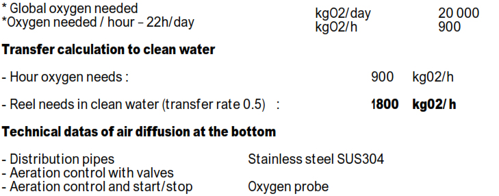
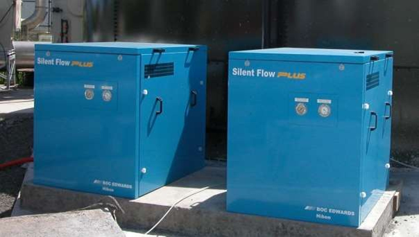
- 5 air blowers, rotary piston without friction, type ROOTS, with electric for 6000 m3/h to 650 mbar and 200 kW electric engine
The air blown by diffusers in the lower part of the basin creates a rising current in the liquid mass and a sweeping over the entire bottom of the structure thus reducing all the submersible media in the vicinity of the diffusers.
By air blower installed, the following equipment is provided:
- 1 (one) mounting frame of the booster and its engine
- 1 (one) suction silencer
- 1 (one) outside air intake with dust filter
- 1 (one) safety valve, calibrated on the air pressure
- 1 (one) stainless steel air manifold for the supply of supercharged air
- 1 (one) non-return valve on the compressed air circuit
- 1 (one) series of stainless steel injection rod with valve
- 1 (one) set of diffusers, type IFU very fine bubbles
- Bolts, screws, sptis, etc ...
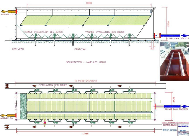
To ensure the treatment of a large flow rate in conventional settling apparatus it would be necessary to have considerable surfaces.
Indeed, by adopting a Hazen speed of 0.5 m/h to treat 750 m3/h, it would be necessary to a settling area of 3 x 325 m2 (circular settling tanks with scrapers).
The implementation of lamellar system can significantly reduce these surfaces. The lamellar decantation is mainly related to the projected area of the plates and the quality of the flow generally translated by the Reynolds number, characteristic of the system.
There are three main types of lamellar decanters. We propose here a lamellar decanter against the current.
The water to be clarified circulates from bottom to top in the opposite direction of the sludge inside tubes formed by plates stacked on top of one another.
The angle of inclination of the tubes formed by the stack of plates must be between 45 ° and 60 ° so that the downward flow of the sludge which is created in the tubes causes with it the finest flocs which would have been driven by the rising water flow.
An inclination angle that is too low prevents self-cleaning of the tubes because the sludge tends to remain attached to the walls.
| Effective length | 97 | nm |
| Thickness of a plate | 3 | nm |
| Angle of inclination | 60 | ° |
| Number of plates per meter | 10 |
The function of this work is homogeneisation of the sludge and preparation before dewatering. Sludge production depends on organic loads inlet. We realize the calculation based on the peak period (5 months with high loads like we made for the biological sizing).
If the BOD inlet is divided by 2, the sludge production will be divided by 2 approximately.
| * Weight of DBO5 to be eliminated per day | Kg | 18 900 |
| * Weight of excess dry matter per Kg BOD5 / day | Kg | 0.85 |
| * Dry weight to be considered per day | Kg | 16 065 [642 m3/day] |
| * Concentration of sludge at the outlet of the decanter | g / l | 25 |
| * Chosen residence time in the storage tank | j | 2 |
| * Silo volume required for 18 900 of BOD5/day | m3 | 1284 |
| * Volume of silo adopted for 2 days | m3 | 1500 |
A mixing system must be installed inside the tank to keep a stable concentration of sludge inside the tank.
For this tank we'll provide.
| Model | POP-I |
| Brand | Landia |
| Propeller velocity | 300 rpm |
| Engine power | 11 kW |
| Quantity | 2 units |
Mixers will be provided with cranes and guard pipes.
The EC EAU PRESS ( screw press technology) consists mainly of a flocculator equipped with a mechanical vertical mixer and a water / sludge separation assembly consisting of a cylinder and a screw (several assemblies can be associated). The speed of the motors is variable. The cylinder is composed of movable disks and discs which, when rotating the screw, rub, allowing a regular and simple cleaning and unclogging.
A solenoid valve allows the feeding of the washing ramp, the self-cleaning of the cylinder allows a very reduced water consumption compared to competing machines in dehydration.
The SCREW PRESS is designed for automatic operation, without human presence during the start and stop phases. Regular visits of controls are obviously necessary to ensure the conformity of the settings as well as the absence of foreign bodies that could obstruct the screw (threads, ...).
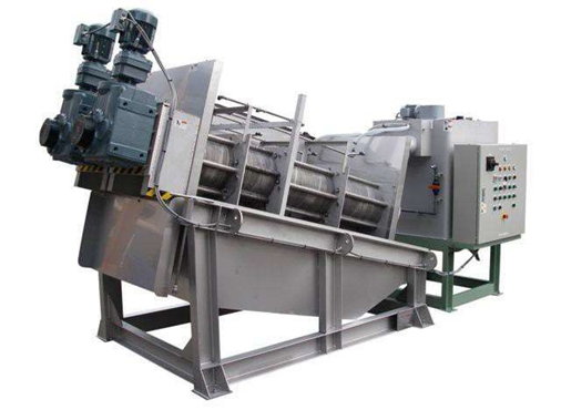
Robust 304L stainless steel construction, the EC EAU PRESS has a filtrate collection tank, an overflow on the feed, a flow measurement on scale, a purge flocculator.
The polymer treatment rate generally used to dehydrate the sludge is of the order of 8 to 10 kg of active product per tonne of dry matter.
To obtain a high dryness strictly greater than 18%, it is necessary to add ferric chloride, poly ferric sulfate or alumina sulfate coagulant. A treatment rate of the order of 3 to 5% of the dry matter is applied. The dose of polymer remaining unchanged.
Sludge at the machine outlet is in the form of a sheet. The recovery by a conveying screw is facilitated by the non-sticky appearance of the sludge coming out of the screw in the form of pellets holding in a pile.
The choice of the nature and the dose of polymer as well as the flocculant / coagulant dosages are essential for the proper functioning of the DISC PRESS. Tests should be carried out before start-up to determine the optimum dose of coagulant / flocculant to be injected.
| Model | ECEAU PRESS MDS453 |
| Quantity | 3 units (only 2 units will work during low season) |
| Length | 4.905 mm |
| Width | 2.240 mm |
| Height | 2900 mm |
| In load weight | 4550 kg |
| ø drum | 3*350 mm |
| Electric power | 6.7 kW |
| Water cleaning shower | 750 L / h |
| Characteristics water washing | 6 m3 / h @ 3 bars |
| Noise | <70 Db |
No vibrations, no necessery special concrete slab
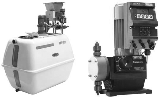
For the necessary flocculation, the mixing and flocculation chamber is included in the press. It is therefore sufficient to provide the supply of a set of preparation and dosage of flocculant.
We have provided the following equipment:
1 PROMINENT or TORO full automatic and continuous preparation unit, including a HDPE or PRV tank, a VR type electro-agitator (P: 1.5 kW), a pump for polymer pump (P: 0.55 kW) or similar, one of a level sensor (with alarm) and set of faucets and accessories.
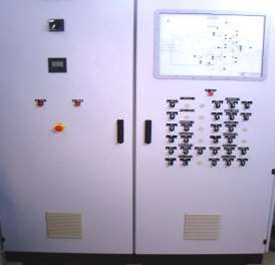
The control and control devices of electric motors are installed in a IP 55 box, designed for wall mounting, or on a bracket.
This box can be installed:
- either in a room: the indicator lights, control buttons and indicator dials (hour meter) will be placed on the cabinet door.
- either outside, exposed to bad weather: only the lights on and fault will be placed on the cabinet door. The controls and dials will be mounted on platinum inside.
This box includes:
* A general disconnect switch, visible from the outside and lockable.
* 380/220/48 Volt transformer for control circuit.
* a departure grounded.
* a general alarm departure in 48 Volts.
* an electrical diagram inside the cabinet.
Wit automation process with computer, alarm list, off site connexion, control by phone, etc.
NOTE: Our project has been established taking into account the current supply of 220/380 Volts + Neutral + Earth, Three Phase 50 Hz.
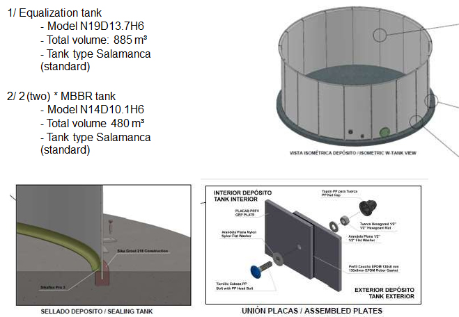
We propose the PRFV (polyester reinforced with glass fiber).
The manufacture of these products in GRP ensures a low maintenance and an impeccable presence over time.
This material provide you an important advantage, it is corrosion free.
Bolted storage W-Tank is a light tank, easy to install and thanks to its corrosion-free composition.
The plates of storage W-Tank© are manufactured by flex molding process.
The Flex Molding process is used to obtain reinforced plastic pieces with high glass fiber content, arranged in the direction of the stress, which leads to high mechanical strength.
It consists of injecting a reactive polymer under pressure into the mold which contains the reinforcement in form of fibers, all of which is done in a controlled vacuum environment.
This process of impregnation (Flex Molding) is used to build pieces in a closed mold, making it an ecological process by eliminating emissions and consumables